|
Dirty-South Blues Harp forum: wail on! >
59BMRI bias tech ?s 5f6H??
59BMRI bias tech ?s 5f6H??
Page:
1
bonedog569
579 posts
Jul 31, 2012
9:20 PM

|
I installed the Kendrick bias pot and upped the dropping resistor. Trying to get a bias reading via the shunt method did not work for some reason.
black probe to one of the output tube plates (brn or blu) , red probe to cetertap red wire on CP23 I believe. Meter set up for ma readings - I get 0000. Any idea's why? It's worked with the same meter on my other amps.
I ordered some 1ohm 3 watt R's for mouser and will instiall when they arrive.
To clarify - I cut the yellow wire from pin 8 to the board (the wire to ground) , and solder in the 1ohm in series with it - correct?
bias theory review:
1) the bias voltage is a negative voltage applied to the grid
2) increasing resistance via bias pot reduces the negative voltage to grid
resulting in higher or 'hotter' bias current - decreasing resistance increases neg. voltage to grid and reduces current to bias 'colder'
go some bias targets for me? I am liking what I'm getting when set a little colder than stock. (a bit lower resistance via bias pot)
gripes department:
fwiw - I still hate soldering to pcbs! ugh! Loosening teh board up to get underneath was a bit of a pain too. I didn't feel confident just grafting to the old leads - they loosen up on the board as soon as the iron touches them.
----------
|
5F6H
1299 posts
Aug 01, 2012
5:28 AM
|
Hi Bonedog,
"I ordered some 1ohm 3 watt R's for mouser and will instiall when they arrive.
To clarify - I cut the yellow wire from pin 8 to the board (the wire to ground) , and solder in the 1ohm in series with it - correct?" Yes, I solder one resistor leg so that it links pins 1 & 8 and this is where I place the meter probe, so both ends of the wire are supported during readings. The free end of the 1ohm resistor (stood up from the socket) can go to the yellow ground wire to the PCB like you say, or it can go to ground on the chassis floor, say to a tube socket bolt & solder tag (possibly not the easiest option on an RI, depends on the lay of the wires.
The Kendrick kit replaces R41 with a cermet pot (?) as the load for the bias circuit, so yes, more resistance here results in more negative voltage & LESS idle current.
CP23 is the B+, so I can't see anything wrong with your procedure (meter set to <200mA dc). Checked the meter's low current fuse? - I tend to use bias probes so I don't keep blowing my low mA meter fuses when forgetting to switch from mA to vdc ;-)
Depending on B+ voltage I'd suggest -55vdc minimum negative voltage at pin 5 of the 6L6s, maybe -65vdc or more if looking for colder idle, very high B+ amps can be around -70vdc. It may very well be possible to bias so cold that there is no current at idle, especially with a 5U4G rectifier, then the amp makes no sound...so start at -60v?
Minimum 6mA to <15mA per tube for cooler settings (not all tubes sound good this low), 15mA+ to late 20's for "regular"...up to mid 30's for "hot".
PCBs - Ha. Use a small iron on the cooler side & a quick dab. It's never what I call "fun". Sometimes existing component legs can make life easier, like the R39 mod, fitting the new resistor between the "+" legs of C20 & C21 makes for an easy & secure job.
----------
www.myspace.com/markburness
http://www.facebook.com/markburness
Last Edited by on Aug 01, 2012 5:30 AM
|
tmf714
1199 posts
Aug 01, 2012
6:00 AM
|
Regarding the shunt method-test leads need to be run to the CURRENT input jacks-then use the 200ma DC range.
I use the Bias Right tool-much easier and MUCH less dangerous.
When using the shunt method,be aware of the risk of electrocution-the meter set to CURRENT is the equivalent of a straight wire-when you connect one probe to high voltage,the other probe also carries the same high voltage.
If you drop one end of the probe on your arm or leg,it WILL electrocute you. Same for the chassis-a huge spark -a melted probe-a blown meter fuse at least,but better than it landing on your leg or arm.
Be extra careful when using the shunt method-if your not sure what to probe,don't probe it!!!
P.S.- I used 30MA on my 91 Bassman RI-I also had a Hoffman point-to-point kit installed with NOS tubes-
Last Edited by on Aug 01, 2012 6:03 AM
|
5F6H
1300 posts
Aug 01, 2012
6:35 AM
|
Good points TM714, 'transformer shunt' bias reading isn't recommended for novices, even "old hands" at this kind of thing should be using meter leads terminating in clips/wire grabbers & not trying to get readings handheld. I know Bonedog has experience around tube/high voltage circuits, so advice is aimed at him specifically.
In fact, safety-wise (for those with suitable experience & know how), I recommend using clips/wire grabbers to ascertain all live meter readings, powering down & disconnecting the amp from the wall between making & remaking connections. Stand back & just use the power & standby to control procedings, rather than grabbing at meters & leads. As well as idle current readings via transformer shunt, there are lots of other potentially lethal areas in a live, open tube amp (though perfectly safe in cabinet & properly enclosed, just like TVs, radios, etc).
All in all bias probes are the best route unless you do this kind of thing everyday.
----------
www.myspace.com/markburness
http://www.facebook.com/markburness
|
walterharp
918 posts
Aug 01, 2012
9:08 AM
|
yeah, and one hand in your pocket
|
bonedog569
581 posts
Aug 01, 2012
9:24 AM
|
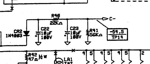
I may have futzed up again. The insructions with the Kendrick pot are pitifull. It does mention R41 - but possibly because I was looking at 5F's myspace mod page, and my amatuer reading of the schematic - I replaced the R40 22K resistor instead of R41. I thought the tiny pot looked a bit small for the job - it's meant for the voltage divider to ground. This also explains my inverse assesment - on R40 more resistance = less neg. voltage, - on R41 more resistance would mean more neg. voltage
I should replace the 22K on 40 and switch the pot to R41 - yes?
re. cautions : Thanks guys - I work with 110/220 VAC all the time - and though cautions, tend to treat B+ voltage a bit like it's 110 - when it's actually more deadly. The reminders don't hurt.
----------
Last Edited by on Aug 01, 2012 9:25 AM
|
5F6H
1301 posts
Aug 01, 2012
10:11 AM
|
Hi Bonedog,
The cermet pot is wired as a rheostat (variable resistor)? Only 2 terminals are used (maybe one on its own & the other 2 are tied together?). If so, I wouldn't disturb the pot you fitted, just dial it back down to 15K...in fact you will be able to leave R41 just as it is at 56K, if you can adjust R40 from a few K up to 22K you have still fitted a bias trim pot (bigger the R40 value, less neg voltage & the hotter the idle current), just on the dropping side of the voltage divider, rather than the load.
You don't really need to know the exact value of R40 if your meter can't read values in situ, it's just a means to an end, just go by neg voltage at pin 5, I'd monitor pin 5 of the 6L6 socket with the tubes removed, until you get into ball-park negative voltages.
If your tubes haven't glowed red yet, no harm done! ;-)
----------
www.myspace.com/markburness
http://www.facebook.com/markburness
|
5F6H
1303 posts
Aug 01, 2012
10:28 AM
|
@ walterharp - "yeah, and one hand in your pocket" and the other one is giving a high 5? ;-)
----------
www.myspace.com/markburness
http://www.facebook.com/markburness
|
bonedog569
583 posts
Aug 01, 2012
12:43 PM
|
I was able to get bias currrent readings with a different meter (attached with alligator clips - thank you) - and the new pot is working as it should to adjust current. 25.5 ma on one tube, 24ma on the other - sounds pretty good to me right now. I'll experiment more later.
Is there much /any current flowing through that pot? I wouldn't think so - but I am concerned that if there is, - it may not be rated to handle it. - It looks so puny and is housed in plastic.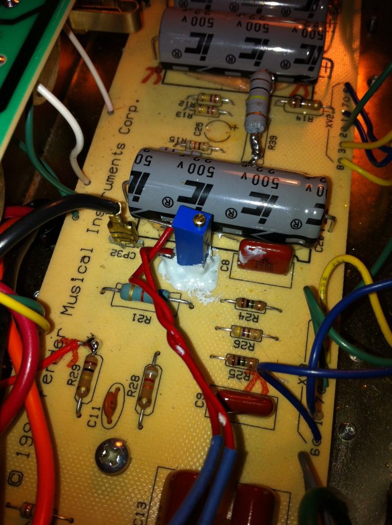
I wrote Kendrick to ask if it might be an issue and haven't heard back yet. - I'll keep an eye on it for now.
fyi - the R39 at 100K dropped voltage a bit too much so I wired a second 180K resistor in parrallel underneath it - at least till I get an 80k in stock. I am now getting 95volts on the AT7 plate.
I just ordered a eurotubes bias-rite kit by the way, - for $25 I don't know why I watied this long.
Thanks again all --- especially Mark (5F) your help as always, is much appreciated.
----------
Last Edited by on Aug 01, 2012 12:44 PM
|
5F6H
1304 posts
Aug 01, 2012
12:55 PM
|
Current in the bias circuit is so little as to be of no concern (~1mA/<100mW dissipation), that's a 750mW pot & plenty sturdy enough, Fender even used 250mW resistors at times.
----------
www.myspace.com/markburness
http://www.facebook.com/markburness
|
Post a Message
|