MrVerylongusername
2399 posts
Jul 10, 2012
12:54 PM

|
Are you 100% certain about the pin numbers on the op amp IC?
This is one of the two posts I worked from:
MIKEMOJO PLANS ...snipped...

This is a simple, easy to build, and foolproof circuit.
The 741 op amp (operational amplifier - originally
designed to do mathematical operations in stone age analog
computers, but the circuit obviously has other uses) is
ancient, proven, cheap, and stupid simple.  It also has
poor high frequency response, which is desirable for
harp mic applications.  For example, it won't oscillate
at some weird radio frequency if you're a little sloppy with
your wiring.

Use two regular 9 volt batteries in series. The mic ground
and output ground go to the connection between the two
batteries. Off/on switch can break the connection between
the two batteries. The op amp symbol is a triangle (yeah,
I know, mine isn't exactly perfect, but you'll recognize
it).

The 741 op amp is in an 8 pin DIP (dual inline
package) (which means it has 4 pins per side). I recommend
using a socket and doing your wiring in advance.

Pin 1 on the 741 has a dot over it. The numbers go in a
"U" shape. 1 thru 4, and then starting at the end opposite
pin 1, 5 thru 8 - so pin 8 is directly opposite pin 1.

Pins 4 and 7 are - and + power respectively.

The op amp output is shorted to the inverting input. This
feeds power back into the input eliminating losses and
making it infinite impedance, which your mic will like a
lot! Gain is clamped at 1 (unity), so it will neither
increase nor decrease your mics signal. However, if you
build it into the mic shell, you may notice more "natural"
highs (which is good). This is because the cable
capacitance acts as a "tone control" and bleeds off highs.
It also skews phase, so you may notice that your mic
sounds "more precise".


          o--------o
          |        |
          o2|\     |
            | >6---o-----o Out
o----------3|/ 741 op amp

(viewed from underneath)

input sleeve o-----------------o output sleeve
   input tip o---o      battery
 input ring      |       clip
       o         |  o----O(+)--o to output jack ring
       |         |  |
       |   1  2  3  4  o-------output jack tip
       |       \       |
       |        \      |
       |   8  7  6  5  |
       |      |  |     |
       |      |  o-----o
       |      |
       o------o


Connect the Positive of battery A to pin 7, and negative of
battery B to pin 4.

Connect the remaining two leads to the ring and sleeve of your
input jack, or (better yet) separately to the rings of input
and output jacks.  Connect the sleeve connections of the two
jacks together.

I use 1/4" stereo female "guitar" type connectors.  These have
a tip, ring, and sleeve contact.  For the MikeMojo, these MUST
be used with standard MONO cables, because the ring and sleeve
are shorted when you plug into both jacks.  This is our "power"
switch.

I use a pair of stereo 1/4" jacks.  When either is unplugged,
the Mojo is turned off.  You could use a single jack, connect
the two grounds together, one battery lead to ground, and the
other to the ring of the stereo jack.  If you build it into
the mic, connect one battery lead to sleeve and the other to
ground.

Use two 9 volt batteries.  Build the board, and after
checking all connections, then install the IC into the socket.
Make sure you don't accidentally bend any of the pins under
the op amp. Insert it firmly and all the way. If you build
this into the mic, the output goes to the cord center
conductor. If you build this into a box, plug the mic into
INPUT (use a 1/4" jack, or whatever), and your amp input to
the OUTPUT (ditto 1/4" jack). Make sure you mark the box
as to which is input and output. Not that it'll hurt
anything, but it'll save you a little grief at gigs.
|
MrVerylongusername
2400 posts
Jul 10, 2012
2:09 PM
|
blimey! a google image search for "micmojo" is very entertaining (not work safe!!!)
Anyway, once I'd got over the distraction I drew this, if it helps:
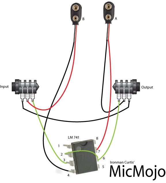
[Obviously it'd be easier to join pins 2 and 6 underneath, but I've shown it this way for clarity. Easier to work with an IC holder, do all the soldering and then plug the chip in. Safer that way too: you don't heat damage the IC]
Last Edited by on Jul 10, 2012 2:17 PM
|